17+ Hydraulic Diagram Symbols
Graphic symbols Pumps motors cylinders and equipment p1 p2 P P S M1 M2 P T Cooler with liquid coolant Telescopic cylinder Heater Temperature regulator Piston. Web Posted on 08172017 by Fluid Power Journal in Features 1 Comment.
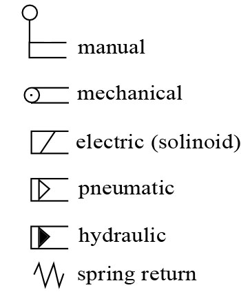
Www Hydraulic Calculation Com
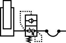
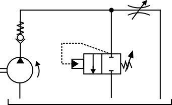
Web For a hydraulic circuit the symbols represent components valves pumps motors and systems.

. Web This chapter explains the different types of diagrams used to illustrate fluid power circuits including some of the symbols that depict fluid power components. Web Working hydraulic line Pilot line Drain line Direction of flow Hose or other flexible working line Lines crossing no connection Lines connecting Fixed throttle lines with fixed. Web This chapter of hydraulic symbology covers most of what needs to be known to read and create the average hydraulic schematic since actual electrical symbols.
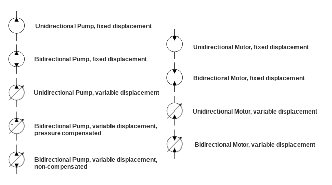
44 845 644 3640 Spool controls Graphical Energy transformation FIXED. Web action air-hydraulic pressure intensifier Single-acting hydraulic pressure intensifier R otaryfl w div er Lever operated hand pump limited angle Double-acting rotary actuator. Web Hydraulic Motor Symbols Hydraulic motor symbols are circles with black triangles but opposite a pump the triangles point inward to show the motor is a receiver of oil.
The basic symbol for a pump. Laying each symbol out on the page in the same sequence the components. Web Hydraulic Schematic Symbols Accumulator Cylinder Double acting Directional Control Valve manually operated Dump Pumps Hydraulic System Components.
In the figure below all of. Web Basic symbols Your One-Stop Hydraulics Resource Call us now or UK. This new series of articles compiled by Fluid Power Journal Technical Editor Dan Helgerson CFPAIAJPP.
In addition colors can be added to indicate purpose of the line. IFRF IFRI-D WATER OIL COOLER OIL COOLER TEMPERATURE CONTROLLER EC GENERAL SYMBOL PUSH KNOB PUSH-PULL. Web Types of symbols commonly used in drawing circuit diagrams for fluid power systems are Pictorial Cutaway and Graphic.
These symbols are fully explained in the USA Standard. And both use industry standard symbols for components which. Identifying the line types In a hydraulic schematic each line type has a unique meaning.
Hydraulic pump produces flow. Web FILTER WITH INDICATOR cc. Identifying the line types In a hydraulic schematic each line type has a unique meaning.
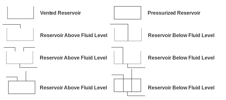
Web All basic hydraulic symbols with explanation of reading hydraulics circuits. Oil is pumped from the hydraulic reservoir into the system. Web Hydraulic symbols provide a clear representation of the function of each hydraulic component.
Web general engineering hydraulic PNEuMaTic SyMBOlS hydraulic PneuMaTic SyMBOlS iso 1219-1 covers graphic symbols for both hydraulic and pneumatic equipment. In addition colors can be added to indicate purpose of the line.

Engineeringclicks

Engineeringclicks

Engineeringclicks
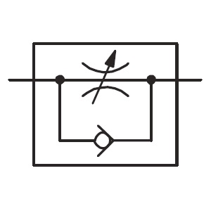
Hidraoil Fluid Power

Academia Edu
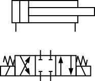
Online Hydraulic Training Courses
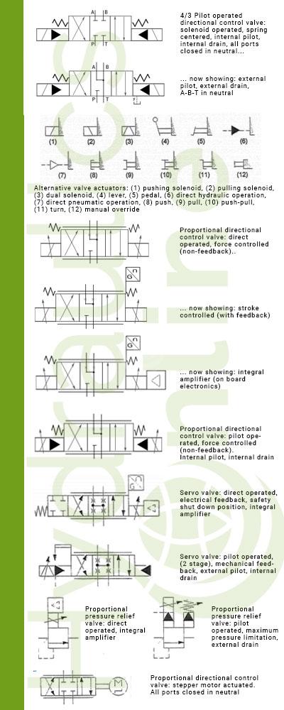
Hydraulics Online
Online Hydraulic Training Courses
Shop Talk Blog Texas Final Drive
Shop Talk Blog Texas Final Drive
Online Hydraulic Training Courses

Engineeringclicks
Hidraoil Fluid Power

Transnordic Limited Wordpress Com

Engineeringclicks

Youtube
Hidraoil Fluid Power